Introduction
Although JST XH connectors are well designed, issues such as poor crimping and contact failures can occur during installation. Drawing on extensive installation and troubleshooting experience, Kidisoii has developed a comprehensive practical tutorial. This article details the installation steps, required tools, crimping techniques, and common troubleshooting methods for JST XH connectors, along with Kidisoii’s proprietary improvements to help engineers quickly identify and resolve problems.
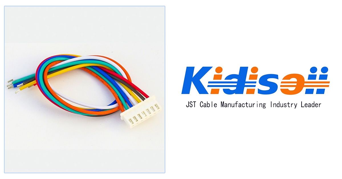
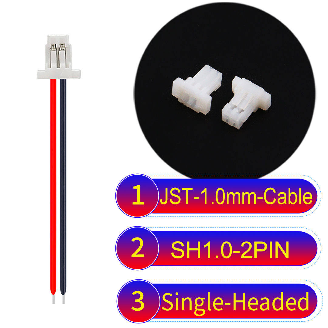
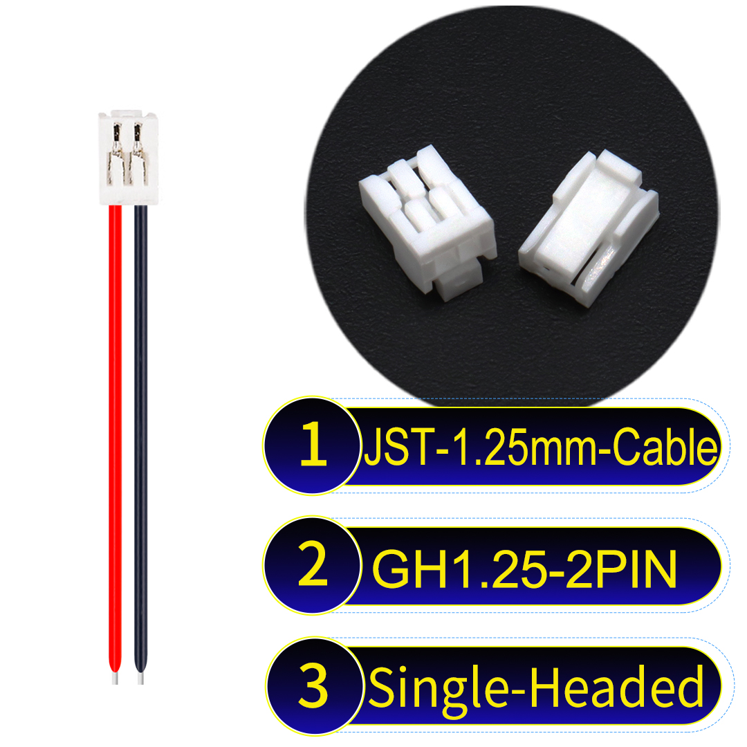
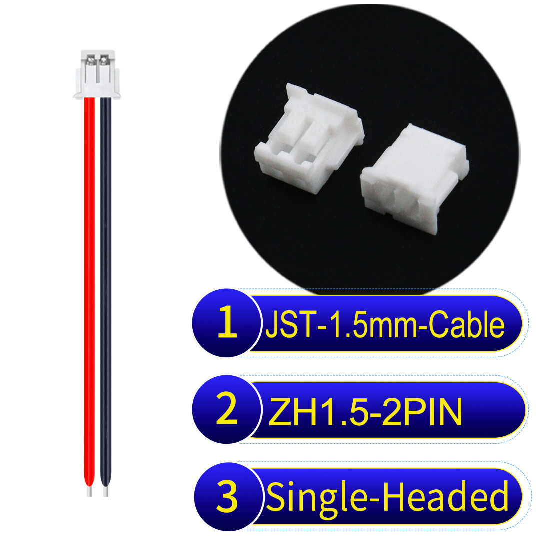
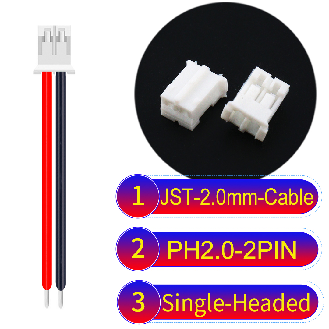
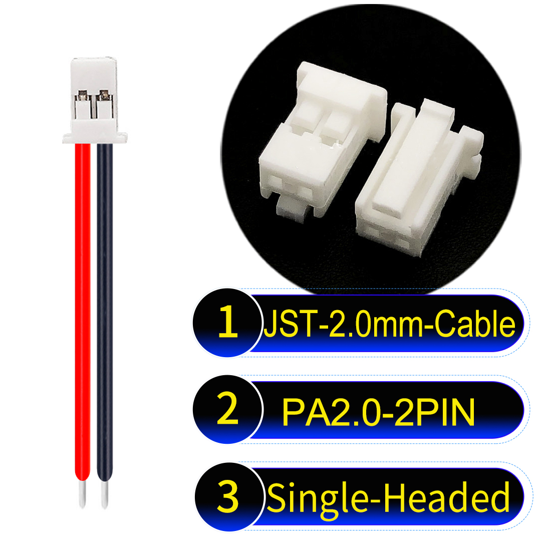
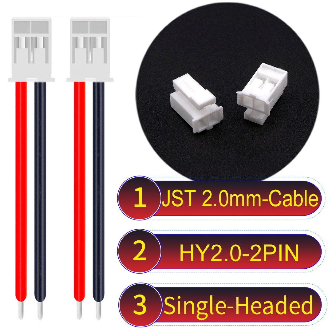
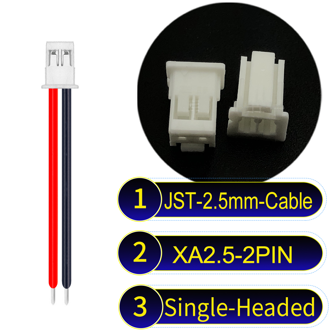
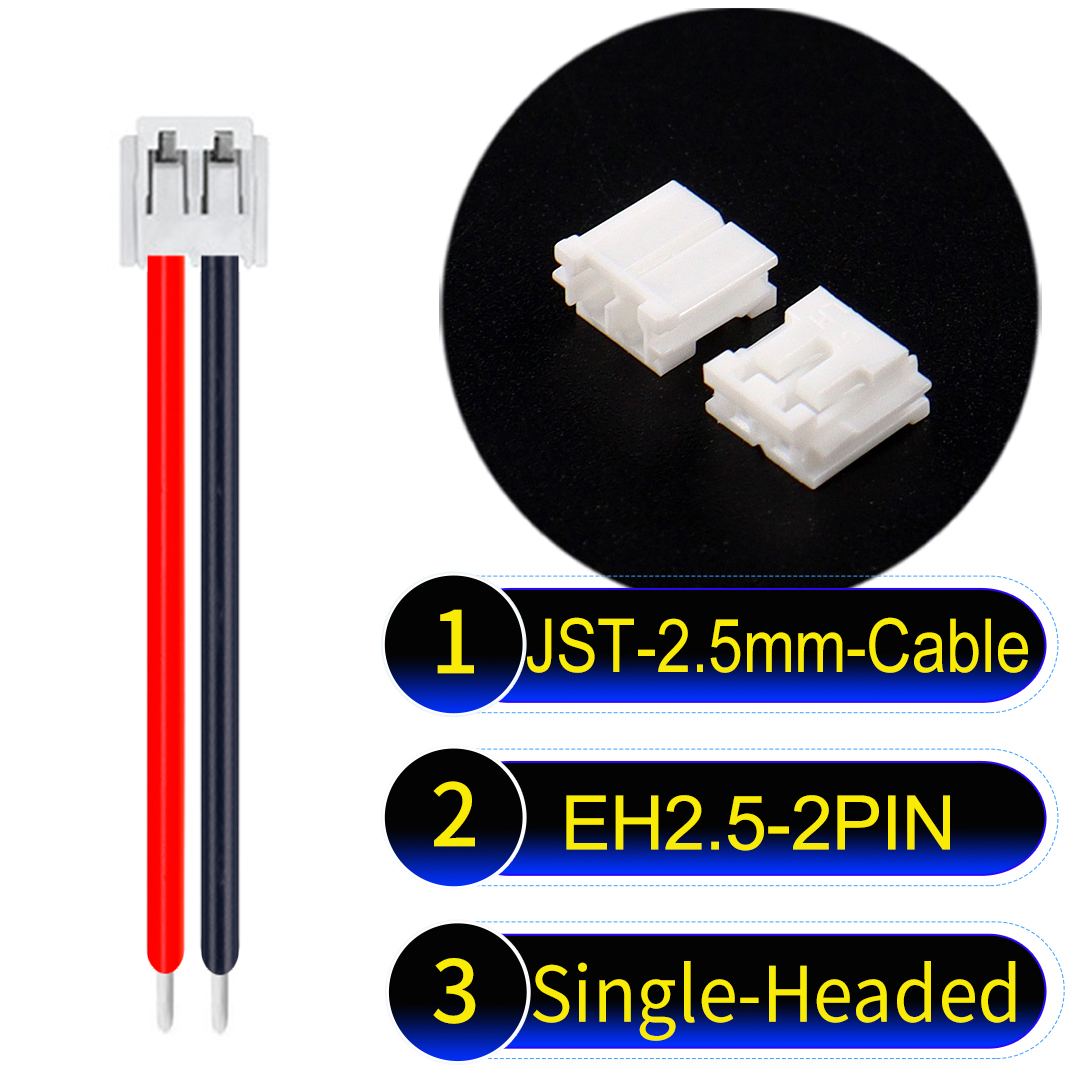
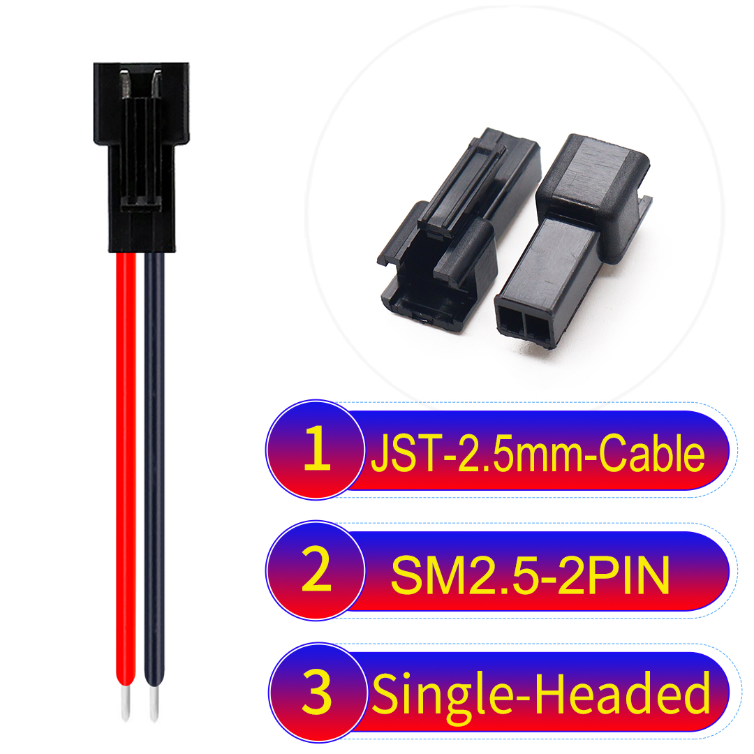
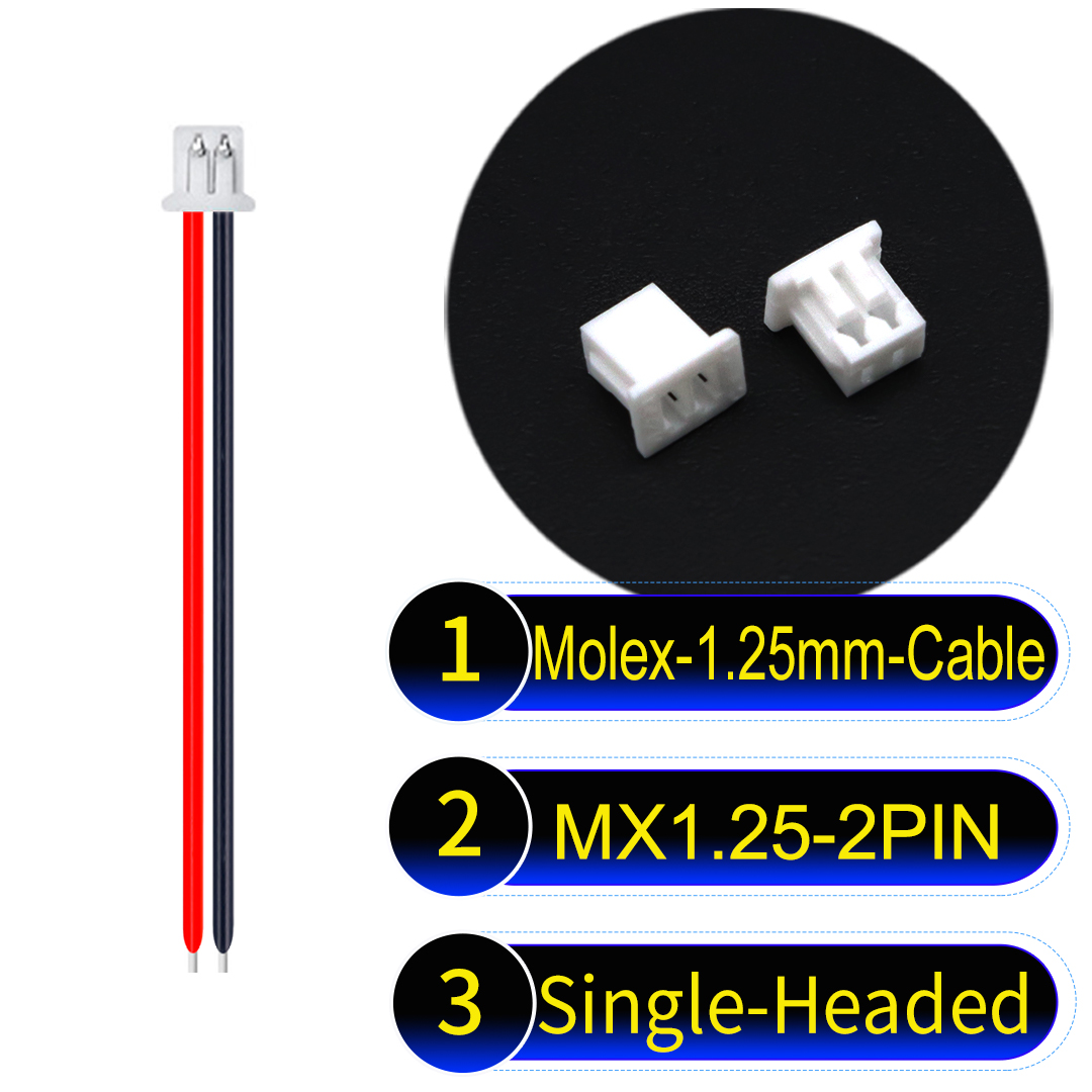
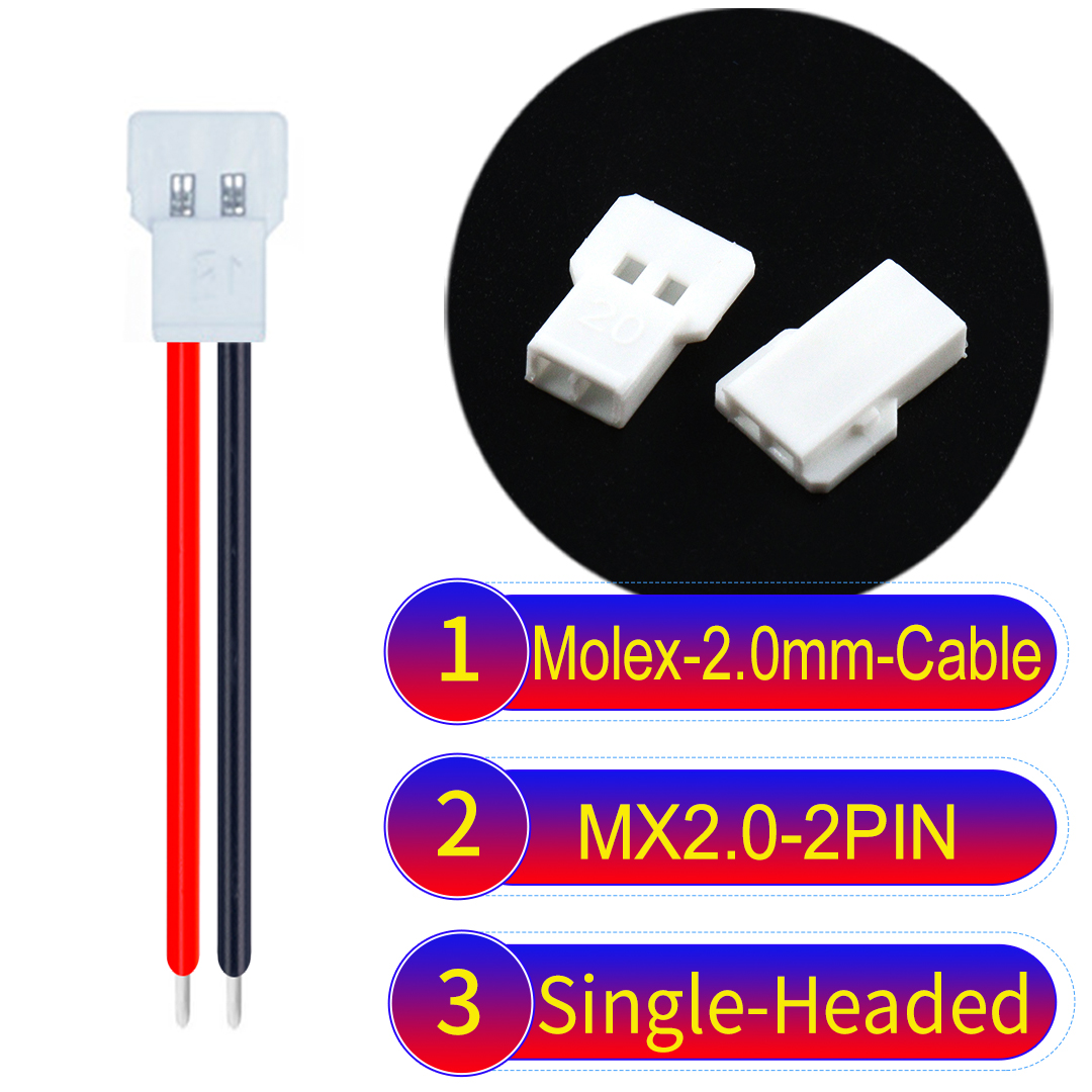
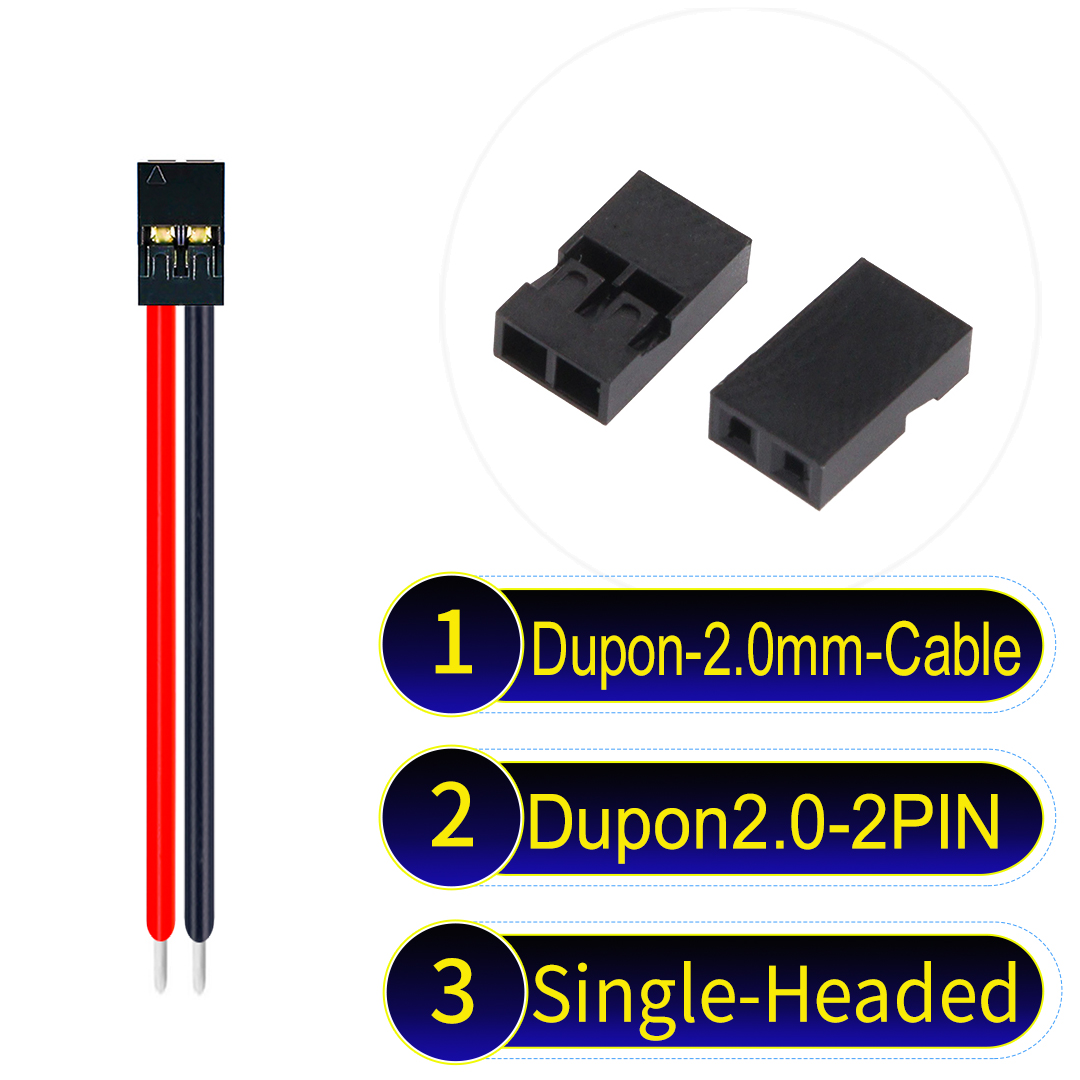
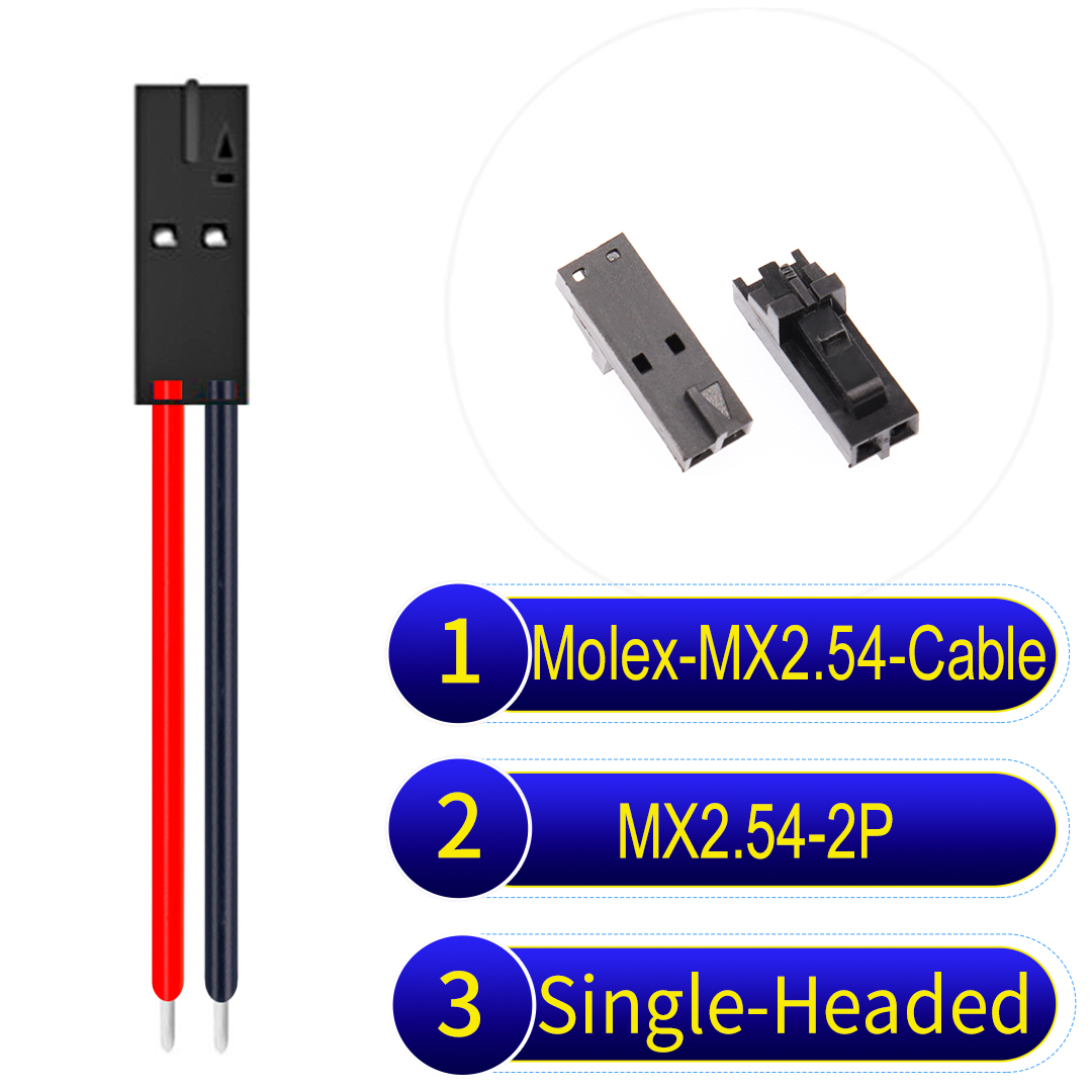
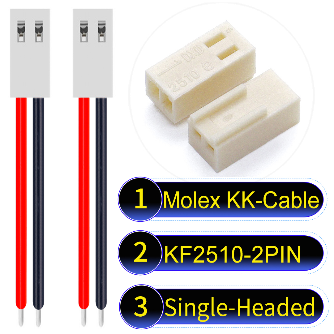
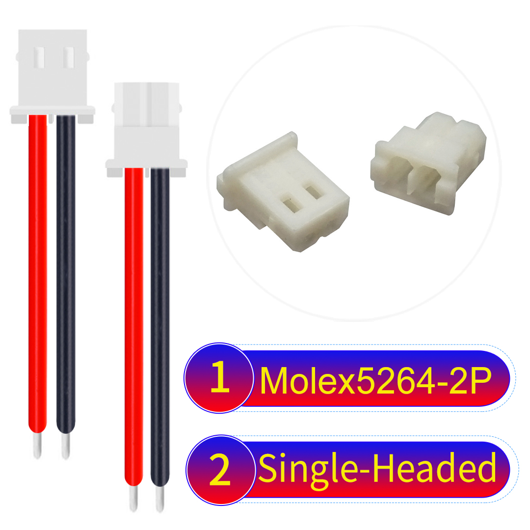
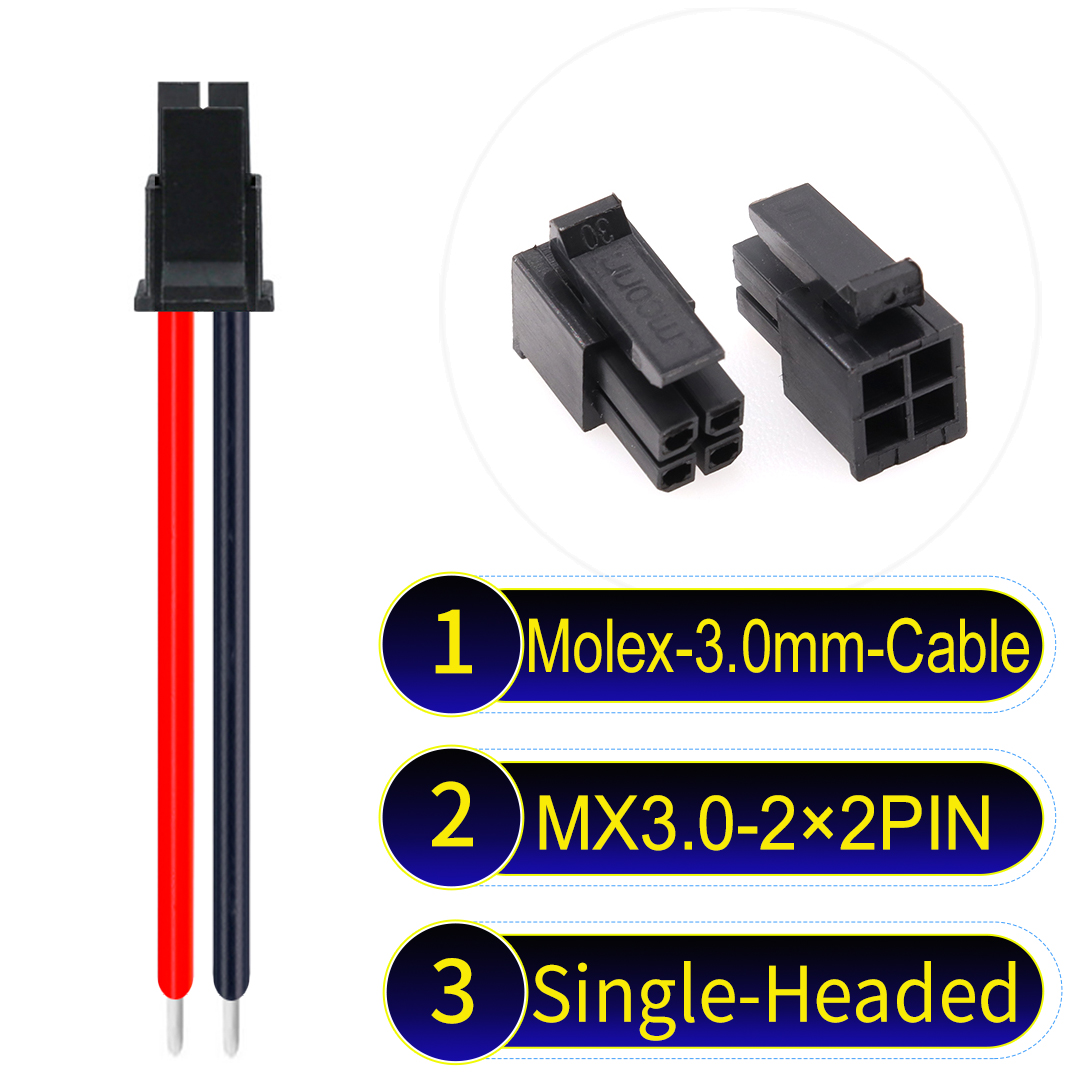
High-performance 7-pin JST XH cable designed for reliable electronic connections.
1. Pre-Installation Preparation
1.1 Tools and Materials
- Professional crimping pliers (e.g., IWISS series, compatible with Kidisoii’s dedicated calibration tools)
- Wire strippers (suitable for AWG22 to AWG28 wires to ensure an accurate stripping length)
- Digital calipers and microscopes for measuring crimp height and stripped lengths
- Genuine JST XH connectors along with Kidisoii’s improved terminals
1.2 Environmental and PCB Design Checks
- Verify that the PCB drill sizes and layout match the connector specifications.
- Maintain a stable room temperature to avoid variations that might affect crimp quality.
2. Correct Installation Steps
2.1 Wire Stripping and Organization
- Follow the datasheet precisely for a stripping length of 2.1–2.6 mm so that the conductor fully enters the terminal without the insulation entering the crimp area.
- Kidisoii recommends using its own automated wire stripping tool to ensure consistency.
2.2 Terminal Pre-Treatment
- Before crimping, remove the terminals from the carrier strip by gently bending them multiple times so that the insulation clamp sides become parallel, preventing rotation during installation.
- Check that the locking hooks are intact to ensure proper locking after crimping.
2.3 Crimping Operation
- Use Kidisoii’s dedicated crimp calibration tool to set the crimp height to the standard value (0.75±0.05 mm for AWG24 wires).
- Slowly close the crimping tool to observe that both the conductor and insulation areas are properly crimped.
- After crimping, measure the crimp height with digital calipers to ensure conformity with the standard.
2.4 Insertion and Assembly
- Insert the crimped terminals into the connector housing, ensuring the locking hooks and the housing slots fully engage. A “click” sound indicates proper locking.
- Test-fit the connector on a prototype board to verify that all pins align with the PCB holes before final assembly.
3. Troubleshooting Common Problems and Kidisoii’s Improvements
3.1 Poor Contact
- Symptoms: Abnormal resistance readings and intermittent power issues.
- Steps:
- Check if the crimp is complete by measuring the conductor crimp height.
- If discrepancies are found, refer to Kidisoii’s troubleshooting manual and re-crimp the terminal accordingly.
3.2 Terminal Loosening or Failure to Lock
- Symptoms: Connector looseness during insertion or no “click” sound.
- Steps:
- Verify that the terminal pre-treatment was performed correctly.
- If the locking hook is deformed, use Kidisoii’s specialized adjustment tool.
- Check the PCB drill size; if necessary, enlarge the holes slightly.
3.3 Kidisoii’s Original Maintenance Handbook
- Kidisoii has developed a “Connector Troubleshooting and Maintenance Handbook” that documents common issues and quick solutions, helping engineers rapidly locate and resolve problems while reducing maintenance time.
4. Conclusion
By following detailed installation steps and troubleshooting methods, combined with Kidisoii’s proprietary tools and maintenance handbook, engineers can significantly improve the installation quality and system stability of JST XH connectors. This practical tutorial and original improvement measures provide solid support for maintenance and design upgrades.